ver-1o
Joule Heating in a Slab under Applied Voltage
Case Description
This verification case isolates the temperature response caused by Joule heating in a one-dimensional proton-conducting ceramic (PCC) slab under an applied voltage. In PCC membranes, the electrical current induced by an applied voltage generates Joule heating, which can increase the local temperature and influence hydrogen-isotope transport. This case verifies the thermal part of the voltage-assisted PCC model independently against an analytical solution for a slab with a uniform volumetric heat source.
This verification case uses a 5 mm half-domain that represents one half of the original 10 mm membrane. The left boundary is held at a prescribed wall temperature, and the right boundary is adiabatic to represent the symmetry plane at the slab centerline. The same electric field as the original full-domain configuration is retained by using a 20 V drop across the full 10 mm membrane.
Case Set Up
The heat equation with a Joule heating source is
(1)
where is the density, is the specific heat capacity, is the temperature, is the time, is the thermal conductivity, and is the volumetric Joule heating rate. The Joule heating is computed from a constant electrical conductivity and a constant applied electric field,
(2)
where is the electrical conductivity, is the magnitude of the applied electric field, is the voltage drop across the full slab, and is the full slab thickness. The half-domain solved in TMAP8 has thickness , with boundary conditions
(3) where is the unit normal vector pointing perpendicular to the boundary surface.
The imposed electric potential is
(4)
where is the constant applied electric-field vector and is a point on the prescribed-voltage boundary. In this one-dimensional verification case, this reduces to . Because the conductivity and electric field are both constant, is uniform in space.
The model parameters used in this case are listed in Table 1. The thermal properties of the BCY20 membrane are taken from Yamanaka et al. (2003). The remaining parameters are selected to simplify the verification problem. The electrical conductivity is set to a constant reference value, and the thermal conductivity is deliberately set lower than the physical BCY20 value to produce a meaningful temperature rise for verification purposes.
Table 1: Values of model properties for the Joule heating verification problem.
| Parameter | Description | Value | Units | Reference |
|---|---|---|---|---|
| wall temperature | 773 | K | – | |
| full PCC slab thickness | 10 | m | – | |
| simulated half-slab thickness | 5 | m | – | |
| voltage applied across the full PCC slab | 20 | V | – | |
| electrical conductivity | 1 | S/m | – | |
| thermal conductivity | 0.014 | W/(mK) | – | |
| specific heat capacity | 120 | J/(molK) | Yamanaka et al. (2003) | |
| density | 6.154 | g/cm | – |
The verification focuses on two aspects of the thermal solution: (1) the transient maximum temperature rise at the insulated symmetry plane, and (2) the transient spatial temperature profile at selected times.
Analytical Solution
Miller (1967) provides the analytical solution for the transient temperature solution under a constant volumetric heat source as:
(5)
where is the thermal diffusivity, and the eigenvalues are described as
(6)
where is the integer mode number in the Fourier series. As , \cref{eq:ver1o_transient} reduces to the steady-state parabolic profile
(7)
Results
Figure 1 compares the maximum temperature rise history, , predicted by TMAP8 against the analytical solution evaluated at the insulated face . The TMAP8 result closely matches the analytical solution, with a root mean square error (RMSPE) of 0.50%.
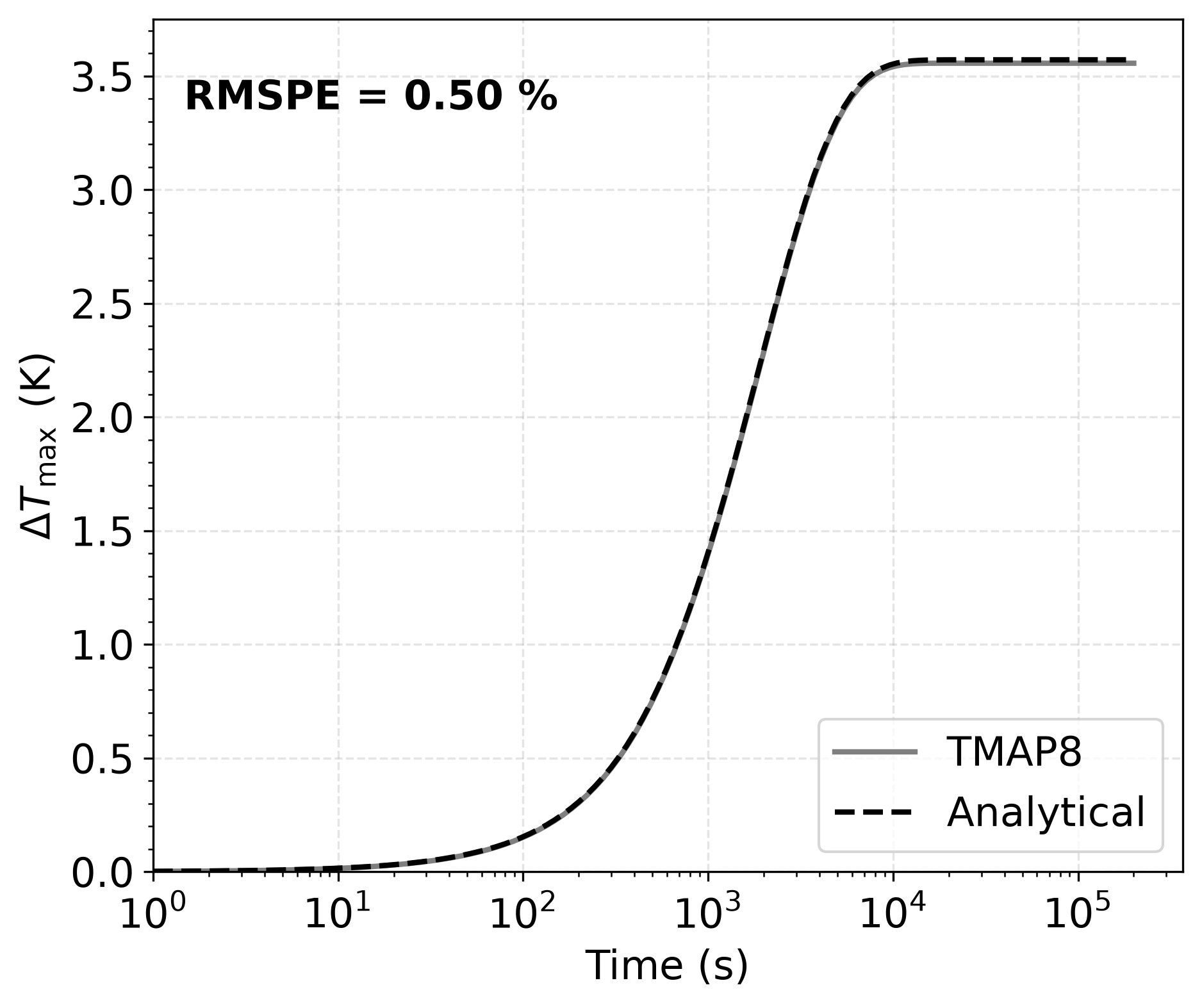
Figure 1: Comparison of the TMAP8 transient maximum temperature rise history with the analytical half-slab solution for a constant Joule-heating source, prescribed surface temperature at , and insulated symmetry plane at .
Figure 2 compares the transient temperature profiles at s and s with the analytical solution. The simulated profiles show excellent agreement with the analytical solution, with RMSPE values below 0.01% at both times.
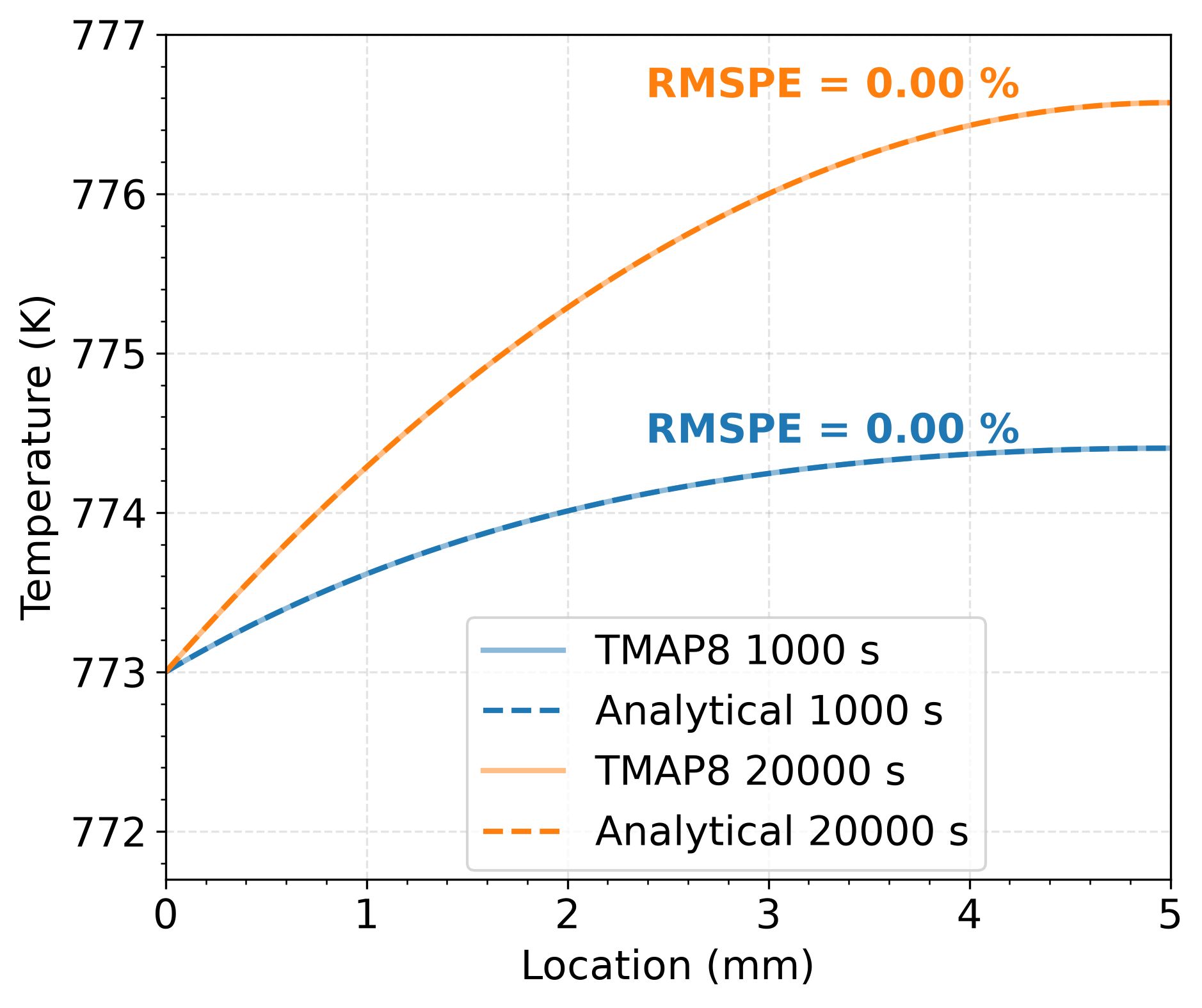
Figure 2: Comparison of the TMAP8 transient temperature profiles at s and s with the analytical half-slab solution.
Input Files
The input file for this case can be found at (test/tests/ver-1o/ver-1o.i). More information about how this is used as a TMAP8 test can be found in the test specification file for this case (test/tests/ver-1o/tests).
References
- Roy W Miller.
Transient heat conduction in finite slabs with position-dependent heat generation.
National Aeronautics and Space Administration, 1967.[Export]
- S. Yamanaka, M. Fujikane, T. Hamaguchi, H. Muta, T. Oyama, T. Matsuda, S.-I. Kobayashi, and K. Kurosaki.
Thermophysical properties of BaZrO and BaCeO.
Journal of Alloys and Compounds, 359(1-2):109–113, 2003.[Export]